Rfid Module Rc522 Kits 13.56 Mhz 6cm With Tags Spi Write & Read for Arduino Diy
Long gone are the days when people used to stand and wait in long checkout lines at the grocery shop. Thanks to the Radio Frequency IDentification (RFID) engineering. With this RFID based walk-through automatic checkout solution, y'all can fill up your cart and walk right out the door. No longer will yous have to wait equally someone rings upward each particular in your cart one at a time. Instead, the RFID tags attached to items will communicate with RFID reader that will detect every item in the cart and band each upwards almost instantly.
For nigh of our RFID based Arduino projects, RC522 RFID Reader/Writer module is a bully choice. It is depression ability, low cost, pretty rugged, easy to interface with and insanely pop amid hobbyists.
What is RFID technology and how does it piece of work?
RFID or Radio Frequency Identification system consists of ii main components, a transponder/tag attached to an object to be identified, and a Transceiver also known as interrogator/Reader.
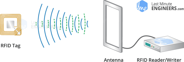
A Reader consists of a Radio Frequency module and an antenna which generates high frequency electromagnetic field. On the other hand, the tag is usually a passive device, meaning it doesn't contain a battery. Instead it contains a microchip that stores and processes data, and an antenna to receive and transmit a bespeak.
To read the data encoded on a tag, information technology is placed in close proximity to the Reader (does not demand to be inside direct line-of-sight of the reader). A Reader generates an electromagnetic field which causes electrons to move through the tag'southward antenna and later on power the chip.
The powered chip inside the tag then responds past sending its stored data back to the reader in the form of another radio signal. This is called backscatter. The backscatter, or change in the electromagnetic/RF wave, is detected and interpreted past the reader which and then sends the data out to a reckoner or microcontroller.
Hardware Overview – RC522 RFID Reader/Writer Module
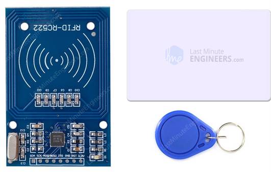
The RC522 RFID module based on MFRC522 IC from NXP is one of the well-nigh inexpensive RFID options that you tin can become online for less than iv dollars. It usually comes with a RFID card tag and key fob tag having 1KB retention. And best of all, it can write a tag, then you can store your some sort of secret message in information technology.
The RC522 RFID Reader module is designed to create a thirteen.56MHz electromagnetic field that information technology uses to communicate with the RFID tags (ISO 14443A standard tags). The reader tin can communicate with a microcontroller over a iv-pin Series Peripheral Interface (SPI) with a maximum data rate of 10Mbps. It likewise supports communication over I2C and UART protocols.
The module comes with an interrupt pin. It is handy because instead of constantly asking the RFID module "is in that location a card in view however? ", the module will alarm us when a tag comes into its vicinity.
The operating voltage of the module is from 2.v to iii.3V, but the good news is that the logic pins are 5-volt tolerant, so we tin can easily connect it to an Arduino or any 5V logic microcontroller without using any logic level converter.
Here are consummate specifications:
RC522 RFID Module Pinout
The RC522 module has total 8 pins that interface information technology to the outside earth. The connections are as follows:
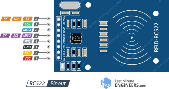
VCC supplies power for the module. This tin can be anywhere from 2.5 to iii.iii volts. You tin can connect it to three.3V output from your Arduino. Remember connecting it to 5V pin will likely destroy your module!
RST is an input for Reset and power-downward. When this pin goes low, hard power-downward is enabled. This turns off all internal current sinks including the oscillator and the input pins are disconnected from the outside world. On the rising edge, the module is reset.
GND is the Footing Pin and needs to be connected to GND pivot on the Arduino.
IRQ is an interrupt pin that can warning the microcontroller when RFID tag comes into its vicinity.
MISO / SCL / Tx pin acts as Master-In-Slave-Out when SPI interface is enabled, acts every bit serial clock when I2C interface is enabled and acts as serial data output when UART interface is enabled.
MOSI (Master Out Slave In) is SPI input to the RC522 module.
SCK (Series Clock) accepts clock pulses provided past the SPI bus Main i.e. Arduino.
SS / SDA / Rx pin acts as Signal input when SPI interface is enabled, acts as serial information when I2C interface is enabled and acts as serial data input when UART interface is enabled. This pin is usually marked by encasing the pin in a square so it tin be used equally a reference for identifying the other pins.
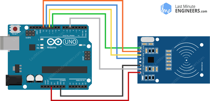
Wiring – Connecting RC522 RFID module to Arduino UNO
Now that we know everything about the module, we can begin hooking it up to our Arduino!
To start with, connect VCC pin on the module to iii.3V on the Arduino and GND pin to ground. The pivot RST can be connected to any digital pivot on the Arduino. In our case, it's continued to digital pin#5. The IRQ pin is left unconnected as the Arduino library we are going to use doesn't support it.
Now we are remaining with the pins that are used for SPI communication. As RC522 module require a lot of information transfer, they volition give the best performance when connected up to the hardware SPI pins on a microcontroller. The hardware SPI pins are much faster than 'bit-banging' the interface lawmaking using some other ready of pins.
Note that each Arduino Board has different SPI pins which should be connected appropriately. For Arduino boards such equally the UNO/Nano V3.0 those pins are digital 13 (SCK), 12 (MISO), 11 (MOSI) and 10 (SS).
If you have a Mega, the pins are different! You'll want to employ digital l (MISO), 51 (MOSI), 52 (SCK), and 53 (SS). Refer below tabular array for quick understanding.
In case y'all're using different Arduino board than mentioned in a higher place, it is appropriate to check the Arduino official documentation before proceeding.
Once you take everything hooked up you are ready to get!
Arduino Code – Reading RFID Tag
Communicating with RC522 RFID module is a agglomeration of work, simply luckily for u.s.a., there'southward a library called MFRC522 library which simplifies reading from and writing to RFID tags. Thanks to Miguel Balboa. Download the library first, past visiting the GitHub repo or, just click this button to download the goose egg:
To install it, open the Arduino IDE, go to Sketch > Include Library > Add .Null Library, and so select the rfid-main.cypher file that you only downloaded. If you demand more than details on installing a library, visit this Installing an Arduino Library tutorial.
Once yous have the library installed, open Examples submenu and select MFRC522 > DumpInfo example sketch.
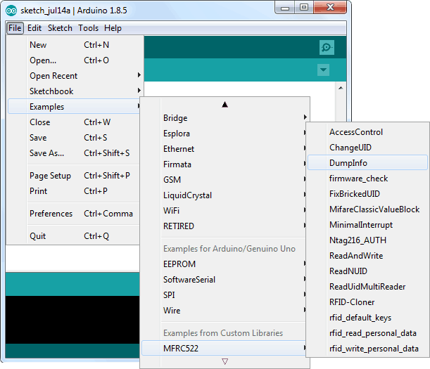
This sketch will not write whatsoever data to the tag. It but tells you if information technology managed to read the tag, and displays some data about information technology. This can be very useful earlier trying out any new tag!
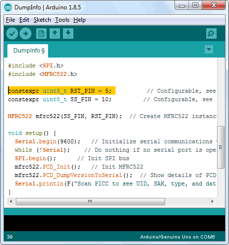
Become to the first of the sketch and brand sure that the RST_PIN is correctly initialized, in our case we're using digital pin #v so change it to 5!
OK, now upload the sketch and open up the Serial Monitor. As soon every bit y'all bring the tag closer to the module, you'll probably get something similar the following. Do not move the tag until all the information is displayed.
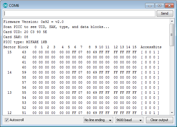
Information technology displays all the useful data about the tag including tag'due south Unique ID (UID), the retentivity size and the whole 1K memory.
MIFARE Classic 1K Memory Layout
The 1K retentivity of the Tag is organized in sixteen sectors (from 0 to 15)Each sector is further devided in to four blocks (block 0 to 3).Each cake can shop 16 bytes of data (from 0 to 15).
That surely tells us nosotros have
16 sectors x 4 blocks ten 16 bytes of data = 1024 bytes = 1K memory
The whole 1K retentiveness with sectors, blocks and information is highlighted beneath.
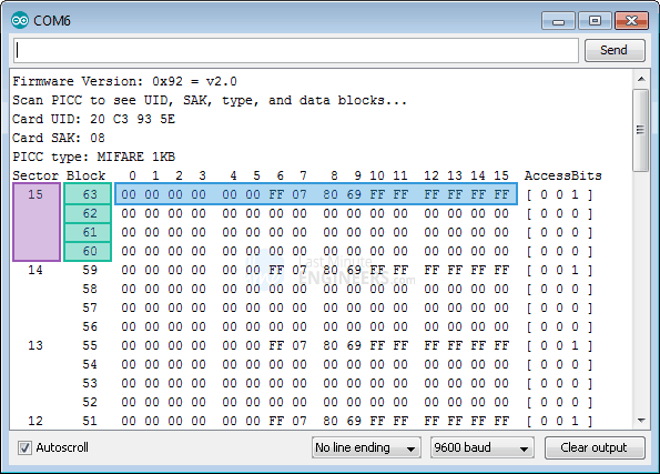

The Block 3 of each sector is called Sector Trailer and contains data called Admission Bits to grant read and write admission to remaining blocks in a sector. That ways only the bottom 3 blocks (cake 0, 1 & 2) of each sector are actually bachelor for information storage, meaning nosotros have 48 bytes per 64 byte sector available for our own use.
Besides The Block 0 of sector 0 is known as Manufacturer Block/Manufacturer Data contains the IC manufacturer data, and the Unique IDentifier (UID). The Manufacturer Block is highlighted in blood-red below.
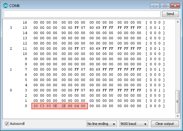
Warning:
It is very risky to overwrite the Manufacturer Cake and information technology may permanently lock the card.
Arduino Lawmaking – Writing RFID Tag
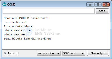
Considering yous take successfully read the RFID tag, nosotros'll move on to our adjacent experiment. The following sketch will do a basic sit-in of writing custom data to RFID tag. Try the sketch out, before we begin its detailed breakdown.
#include <SPI.h> //include the SPI omnibus library #include <MFRC522.h> //include the RFID reader library #define SS_PIN x //slave select pin #ascertain RST_PIN 5 //reset pin MFRC522 mfrc522(SS_PIN, RST_PIN); // instatiate a MFRC522 reader object. MFRC522::MIFARE_Key key; //create a MIFARE_Key struct named 'central', which will concur the menu information //this is the block number we will write into and so read. int block=2; byte blockcontent[16] = {"Concluding-Infinitesimal-Engg"}; //an assortment with 16 bytes to be written into one of the 64 card blocks is defined //byte blockcontent[16] = {0,0,0,0,0,0,0,0,0,0,0,0,0,0,0,0}; //all zeros. This can be used to delete a block. //This array is used for reading out a block. byte readbackblock[xviii]; void setup() { Serial.begin(9600); // Initialize series communications with the PC SPI.begin(); // Init SPI bus mfrc522.PCD_Init(); // Init MFRC522 card (in case y'all wonder what PCD means: proximity coupling device) Serial.println("Browse a MIFARE Classic card"); // Set up the security central for the read and write functions. for (byte i = 0; i < half-dozen; i++) { cardinal.keyByte[i] = 0xFF; //keyByte is divers in the "MIFARE_Key" 'struct' definition in the .h file of the library } } void loop() { // Look for new cards if ( ! mfrc522.PICC_IsNewCardPresent()) { return; } // Select one of the cards if ( ! mfrc522.PICC_ReadCardSerial()) { return; } Series.println("card selected"); //the blockcontent array is written into the menu block writeBlock(block, blockcontent); //read the block back readBlock(block, readbackblock); //uncomment below line if yous want to come across the entire 1k memory with the block written into it. //mfrc522.PICC_DumpToSerial(&(mfrc522.uid)); //print the block contents Series.print("read block: "); for (int j=0 ; j<16 ; j++) { Serial.write (readbackblock[j]); } Serial.println(""); } //Write specific block int writeBlock(int blockNumber, byte arrayAddress[]) { //this makes sure that nosotros just write into information blocks. Every 4th block is a trailer cake for the admission/security info. int largestModulo4Number=blockNumber/4*4; int trailerBlock=largestModulo4Number+three;//determine trailer cake for the sector if (blockNumber > 2 && (blockNumber+1)%four == 0){Serial.print(blockNumber);Series.println(" is a trailer cake:");return 2;} Serial.print(blockNumber); Series.println(" is a information block:"); //authentication of the desired block for access byte condition = mfrc522.PCD_Authenticate(MFRC522::PICC_CMD_MF_AUTH_KEY_A, trailerBlock, &key, &(mfrc522.uid)); if (status != MFRC522::STATUS_OK) { Serial.print("PCD_Authenticate() failed: "); Serial.println(mfrc522.GetStatusCodeName(status)); return iii;//return "3" as error message } //writing the block status = mfrc522.MIFARE_Write(blockNumber, arrayAddress, 16); //status = mfrc522.MIFARE_Write(ix, value1Block, 16); if (status != MFRC522::STATUS_OK) { Series.print("MIFARE_Write() failed: "); Serial.println(mfrc522.GetStatusCodeName(status)); return iv;//return "iv" as error message } Serial.println("block was written"); } //Read specific block int readBlock(int blockNumber, byte arrayAddress[]) { int largestModulo4Number=blockNumber/4*four; int trailerBlock=largestModulo4Number+3;//determine trailer block for the sector //authentication of the desired cake for access byte status = mfrc522.PCD_Authenticate(MFRC522::PICC_CMD_MF_AUTH_KEY_A, trailerBlock, &cardinal, &(mfrc522.uid)); if (status != MFRC522::STATUS_OK) { Serial.print("PCD_Authenticate() failed (read): "); Serial.println(mfrc522.GetStatusCodeName(status)); return three;//return "three" equally error bulletin } //reading a block byte buffersize = 18;//we need to define a variable with the read buffer size, since the MIFARE_Read method below needs a pointer to the variable that contains the size... condition = mfrc522.MIFARE_Read(blockNumber, arrayAddress, &buffersize);//&buffersize is a pointer to the buffersize variable; MIFARE_Read requires a pointer instead of just a number if (condition != MFRC522::STATUS_OK) { Serial.print("MIFARE_read() failed: "); Serial.println(mfrc522.GetStatusCodeName(status)); return 4;//return "iv" as error bulletin } Serial.println("block was read"); } The output on serial monitor will await like this.
Code Explanation:
The sketch starts with including the MFRC522 and SPI library, defining Arduino pins to which RC522 is connected and instantiating MFRC522 reader object.
#include <SPI.h> //include the SPI jitney library #include <MFRC522.h> //include the RFID reader library #define SS_PIN 10 //slave select pin #define RST_PIN 5 //reset pin MFRC522 mfrc522(SS_PIN, RST_PIN); // instatiate a MFRC522 reader object. MFRC522::MIFARE_Key primal;//create a MIFARE_Key struct named 'key', which volition hold the card information Adjacent, we need to define a block in which nosotros are going to store our data. Here sector 0 block 2 is selected. Call up never select block 3 of whatsoever sector. Writing into 'sector trailer' block tin can make the cake unusable.
//this is the block number we volition write into and and then read. int cake=two; Adjacent, nosotros define an array of 16 bytes named blockcontent[16] which holds the message we desire to write into the block. You can delete whatsoever cake by writing zeros.
byte blockcontent[16] = {"Last-Minute-Engg"}; //an array with sixteen bytes to exist written into ane of the 64 card blocks is defined //byte blockcontent[16] = {0,0,0,0,0,0,0,0,0,0,0,0,0,0,0,0}; //all zeros. This tin exist used to delete a block. Next, we need to ascertain an array of xviii bytes named readbackblock[18]. This can be used to read the written contents back. Wait…eighteen bytes? Shouldn't this be xvi bytes? The answer is No. The MIFARE_Read method in MFRC522 library requires a buffer that is at least xviii bytes to hold the 16 bytes of a block.
//This array is used for reading out a cake. byte readbackblock[18]; In Setup role: we initialize the serial communications with the PC, SPI library and MFRC522 object. Nosotros also need to prepare the security key for the read and write functions. Here all six key bytes are fix to 0xFF. Since the cards in the kit are new and the keys were never defined, they are 0xFF. If we had a card that was programmed past someone else, nosotros would demand to know the central to be able to access it. This key would then need to be stored in 'key' instead.
Series.begin(9600); // Initialize serial communications with the PC SPI.begin(); // Init SPI bus mfrc522.PCD_Init(); // Init MFRC522 carte du jour (in case you lot wonder what PCD means: proximity coupling device) Serial.println("Browse a MIFARE Classic carte du jour"); // Prepare the security key for the read and write functions. for (byte i = 0; i < 6; i++) { key.keyByte[i] = 0xFF; //keyByte is defined in the "MIFARE_Key" 'struct' definition in the .h file of the library } In loop function: we first scan if there is a bill of fare in view, if yep, that bill of fare is selected for writing and reading purpose.
// Look for new cards if ( ! mfrc522.PICC_IsNewCardPresent()) { return; } // Select one of the cards if ( ! mfrc522.PICC_ReadCardSerial()) { return; } Serial.println("menu selected"); Wring the block is now very easy, we only need to phone call a custom function called writeBlock() which takes two parameter – one is cake number to which we are interested in writing the information and the data itself.
//the blockcontent array is written into the carte du jour cake writeBlock(block, blockcontent); To check if the write functioning was successful, we need to read the block contents back. This can be done using custom function called readBlock() which over again takes two parameters – one is block number and other is array to shop block contents. You tin apply the PICC_DumpToSerial() function if you want to run across the entire 1k memory with the block written into it.
//read the block back readBlock(block, readbackblock); //uncomment below line if you lot want to see the entire 1k memory with the cake written into it. //mfrc522.PICC_DumpToSerial(&(mfrc522.uid)); Finally, we print the contents of readbackblock array using a for loop and display contents on series monitor.
//impress the block contents Serial.impress("read block: "); for (int j=0 ; j<sixteen ; j++) { Serial.write (readbackblock[j]); } Series.println("");
Arduino Projection
RFID Door Lock Access Control System
Allow'southward create a quick Arduino project to demonstrate how a elementary RC522 RFID reader module can be used to brand a RFID Door Lock Access Command System. Our plan will scan unique ID of each RFID tag when it's close plenty to exist energized by the RC522 reader. If the UID of the tag matches a predefined value (Master tag) that is stored in Arduino memory, the admission will be granted. And if we browse any unknown tag the access will be denied. Great! Right?
This is how the output looks like.
Of course this project could exist interfaced to open doors, switch on a relay, light up an LED, or anything else you can think of.
In case y'all are not familiar with sixteen×2 character LCDs, consider reading (at least skimming) beneath tutorial.
SUGGESTED READING

Before we become to uploading code and scanning tags, let'southward look at the circuit schematic for the project.
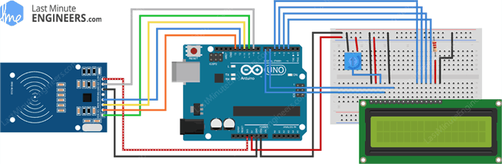
That's information technology! Now, try the below sketch out.
#include <SPI.h> #include <MFRC522.h> #include <LiquidCrystal.h> #define RST_PIN 9 #define SS_PIN 10 byte readCard[4]; Cord MasterTag = "20C3935E"; // Supervene upon this Tag ID with your Tag ID!!! Cord tagID = ""; // Create instances MFRC522 mfrc522(SS_PIN, RST_PIN); LiquidCrystal lcd(7, 6, 5, 4, iii, two); //Parameters: (rs, enable, d4, d5, d6, d7) void setup() { // Initiating SPI.brainstorm(); // SPI bus mfrc522.PCD_Init(); // MFRC522 lcd.begin(sixteen, 2); // LCD screen lcd.articulate(); lcd.impress(" Access Control "); lcd.setCursor(0, 1); lcd.print("Scan Your Card>>"); } void loop() { //Expect until new tag is available while (getID()) { lcd.clear(); lcd.setCursor(0, 0); if (tagID == MasterTag) { lcd.print(" Access Granted!"); // You tin write any code here similar opening doors, switching on a relay, lighting up an LED, or annihilation else you lot can think of. } else { lcd.print(" Access Denied!"); } lcd.setCursor(0, 1); lcd.print(" ID : "); lcd.impress(tagID); delay(2000); lcd.clear(); lcd.print(" Admission Command "); lcd.setCursor(0, i); lcd.impress("Scan Your Carte du jour>>"); } } //Read new tag if available boolean getID() { // Getting ready for Reading PICCs if ( ! mfrc522.PICC_IsNewCardPresent()) { //If a new PICC placed to RFID reader keep return simulated; } if ( ! mfrc522.PICC_ReadCardSerial()) { //Since a PICC placed get Serial and go on return simulated; } tagID = ""; for ( uint8_t i = 0; i < iv; i++) { // The MIFARE PICCs that we use accept 4 byte UID //readCard[i] = mfrc522.uid.uidByte[i]; tagID.concat(String(mfrc522.uid.uidByte[i], HEX)); // Adds the 4 bytes in a single String variable } tagID.toUpperCase(); mfrc522.PICC_HaltA(); // Stop reading return true; } The program is quite simple. At the start we include the necessary libraries, define Arduino pins, create instances of LCD & MFRC522 objects and define master tag.
#include <SPI.h> #include <MFRC522.h> #include <LiquidCrystal.h> #define RST_PIN 9 #ascertain SS_PIN ten byte readCard[4]; String MasterTag = "20C3935E"; // Supercede this Tag ID with your Tag ID!!! Cord tagID = ""; // Create instances MFRC522 mfrc522(SS_PIN, RST_PIN); LiquidCrystal lcd(seven, 6, v, 4, 3, ii); //Parameters: (rs, enable, d4, d5, d6, d7) In setup function, we initialize SPI interface, MFRC522 object and LCD. Following that we print welcome message on the LCD.
void setup() { // Initiating SPI.begin(); // SPI bus mfrc522.PCD_Init(); // MFRC522 lcd.begin(16, 2); // LCD screen lcd.clear(); lcd.print(" Admission Control "); lcd.setCursor(0, 1); lcd.print("Browse Your Card>>"); } In loop role, we await until the new tag is scanned. Once it'southward done, we compare the unknown tag with the primary tag defined prior setup role. That's information technology! If its ID matches master ID, access is granted else denied.
void loop() { //Expect until new tag is bachelor while (getID()) { lcd.clear(); lcd.setCursor(0, 0); if (tagID == MasterTag) { lcd.print(" Access Granted!"); // You tin can write whatever code here similar opening doors, switching on a relay, lighting up an LED, or annihilation else yous can retrieve of. } else { lcd.print(" Admission Denied!"); } lcd.setCursor(0, ane); lcd.impress(" ID : "); lcd.print(tagID); filibuster(2000); lcd.articulate(); lcd.impress(" Access Control "); lcd.setCursor(0, i); lcd.impress("Browse Your Card>>"); } } The cardinal thing in the project is a custom function called getID(). In one case it scans for the new carte du jour, inside a for loopit converts 4 byte of UID into cord and concatenates to create a unmarried cord.
boolean getID() { // Getting set for Reading PICCs if ( ! mfrc522.PICC_IsNewCardPresent()) { //If a new PICC placed to RFID reader continue render false; } if ( ! mfrc522.PICC_ReadCardSerial()) { //Since a PICC placed get Serial and continue return false; } tagID = ""; for ( uint8_t i = 0; i < four; i++) { // The MIFARE PICCs that we employ accept 4 byte UID //readCard[i] = mfrc522.uid.uidByte[i]; tagID.concat(String(mfrc522.uid.uidByte[i], HEX)); // Adds the iv bytes in a single String variable } tagID.toUpperCase(); mfrc522.PICC_HaltA(); // Stop reading return true; } Source: https://lastminuteengineers.com/how-rfid-works-rc522-arduino-tutorial/
0 Response to "Rfid Module Rc522 Kits 13.56 Mhz 6cm With Tags Spi Write & Read for Arduino Diy"
Publicar un comentario